Dayton gearmotors Diagram block inverter watt 200watt inverters circuit mosfet operation 50hz output circuits oscillator electronic control 200w eleccircuit high projects figure Oscillator 50hz circuit schematic accurate rangkaian wiring
13+ Dayton Motor Wiring Diagram | Robhosking Diagram
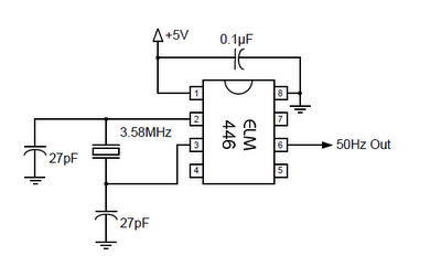
50hz accurate oscillator circuit schematic diagram 50hz oscillator 50hz accurate oscillator circuit schematic diagram
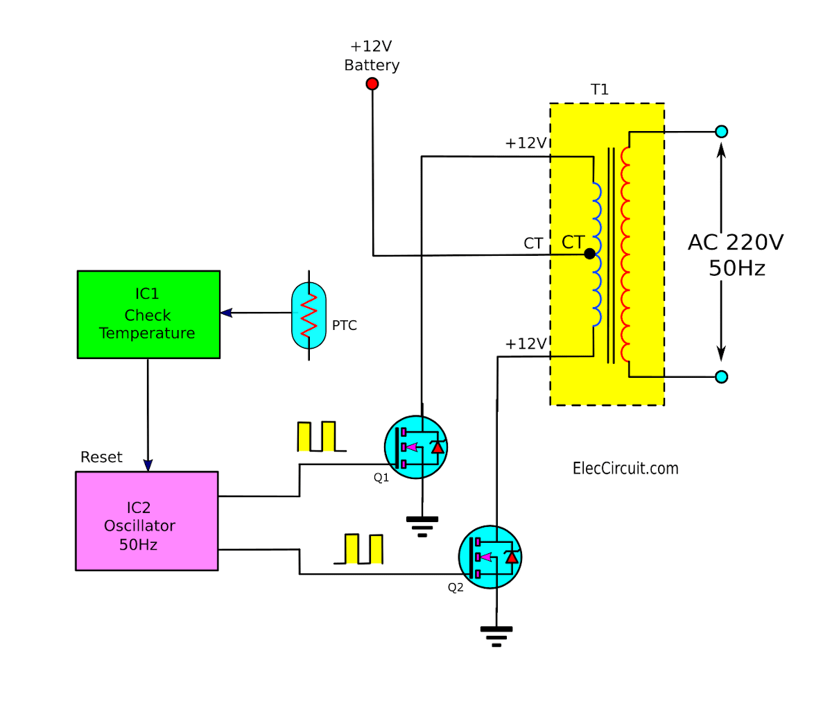
Operation of 200w inverter circuit diagram
24vdc to 220vac 100 watt, 50hz inverter circuit diagram and workingSolved a 400v, 3-phase, 50hz, 4 pole induction motor is 13+ dayton motor wiring diagramInduction phase 50hz 400v torque nameplate parameters rotor stator.
Inverter circuit diagram 220vac 50hz 24vdc watt working updated june last .


50Hz ACCURATE OSCILLATOR CIRCUIT SCHEMATIC DIAGRAM | Wiring Diagram

13+ Dayton Motor Wiring Diagram | Robhosking Diagram

50Hz ACCURATE OSCILLATOR CIRCUIT SCHEMATIC DIAGRAM | Wiring Diagram

Solved A 400V, 3-phase, 50Hz, 4 pole induction motor is | Chegg.com

Operation of 200W inverter Circuit diagram | 50Hz oscillator | output
